Isolines Shape
Intro
Convert images, Shaders or Shape Layers into Contours.
UI
Mode - Determine whether the Contours are generated from an Image Asset, Shader or Shape Layer:
- Image - Use an Image Asset as the source for the Contours.
- Shape Layer - Use a Shape (and Shader) as the source for the Contours.
- Shader - Use a Shader (without a Shape) as the source for the Contours.
The Image and Shader modes are more performant than Shape Layer mode, particularly if Filters are used. If performance is an issue, consider rendering the Input Shape to an image sequence and using that with Image mode.
Input Shape - When Mode is set to Shape Layer, connect a Shape.
Input Image - When Mode is set to Image, connect an image asset. This can be directly from the Assets Window, via an Asset Array or an Asset from Smart Folder Utility.
Time - When Mode is set to Image, set the frame number of a video or image sequence to sample. By default, this is connected to the Composition's Time. Note that where an Input Shape or Input Shader is connected and include properties that change over time, their own Time attributes should be used.
Input Shader - When Mode is set to Shader, connect a Shader.
Size - When Mode is set to Shader, define the world-space dimensions of the area sampled.
Looping - When Mode is set to Image and Looping is checked, any video or image sequence assets will loop.
Source Channel - Select the color component of the input to sample. Alpha, Luma (default), Red, Green or Blue.
- Alpha - Use the input's alpha channel.
- Luma - Use the input's luminance (brightness) channel.
- Red - Use the red component of the input's color channel.
- Green - Use the green component of the input's color channel.
- Blue - Use the blue component of the input's color channel.
Invert Source - When checked, the input's luminance values are reversed before being sampled.
Use Threshold Graph - When checked, the Threshold Graph can be used to remap the input's sampled values.
Threshold Graph - When Use Threshold Graph is checked, draw a graph to remap the input's sampled values. This can be used to squash/stretch the change in luminance values and so create more/ess Contours in those areas.
Extraction Mode - Determine the type of geometry to be extracted from the sampled input:
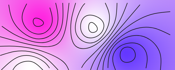
- Isolines - Output open or closed contour lines.
- Filled Regions - Output closed shapes for each band between levels including holes.
- Cell Boundaries - Output the outline of each band, i.e. the dividing lines between filled regions.
Contour Levels - Set the number of Contours created (evenly distributed across luminance values).
Grid Size - Set the size of the sampling grid. Smaller values will result in more accurate/detailed results but may affect performance.
Clean Up Path - When checked, points that are very close together are removed from the output Contours.
Simplify - When checked, points that fall within the Simplify Tolerance are removed.
Simplify Tolerance - Set the maximum deviation to the Contours, in field cells, a removed point may introduce. A higher tolerance will increase performance but produce a more angular, low-poly look.
Output Béziers - When checked, the output Contours are resampled as bézier curves.
Filter Path Size - When checked, paths which are smaller than the Path Size are removed. A path's 'size' is calculated as the longest dimension (width/height) of its bounding box.
Path Size - When Filter Path Size is checked, any Contours with a 'size' less than this value will be removed.
Field Smoothing - Set the amount of blur applied to the sampled field before tracing. This can be used to soften noise and so create less jagged Contours.
Path Smoothing - Set the amount of smoothing to apply to the traced Contours by rounding off the 'marching-grid' steps.
Group By Level - When checked, each Contour is grouped into one mesh. Uncheck to create one child-mesh per Contour so Behaviours can address each one individually.
Sort Mode - When Group by Level is unchecked, determine how the extracted child-meshes are ordered. When Group by Contour Level is checked, child-meshes will always stack in Contour Level order:
- Contour Order - The default order without any reordering.
- Area - Order the Contours based on their individual area from smallest to largest.
- Brightness - Order the Contours based on the luminance.
- X - Order the Contours based on their position in the X axis.
- Y - Order the Contours based on their position in the Y axis.
- Random - Randomly order the Contours. Use Random Seed to reorder.
- Shader Value - Order the Contours by the input's channel value after Invert Source and the Threshold Graph.
Reverse Sort - When checked, the order child-meshes are ordered in is reversed.
Random Seed - When Sort Mode is set to Random, set a random seed value to reorder the Contours.